Dr Pepper
All American
3583 Posts
user info
edit post |
ok here's the scoop:
I have two circuits I wish to control (Overdrive on/off, Torque converter on/off). The connection to the trans has 3 wires, OD/power/TC; the control is simply ground whichever wire for the function I want to have turned on.
Here's where it gets good. I am going to wire a DPDT momentary switch for each circuit - toggle back to engage, toggle forward to disengage the item; this requires a latching circuit to function.
I have no idea how to wire the momentary DPDT into a latching relay, this one for example:
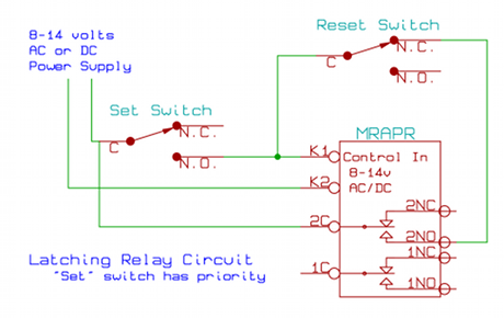
Which is a handy-dandy item i can buy and wire up. http://www.azatrax.com/track-power-relay.html
And honestly, i don't know if that's even what I need.... maybe a DPDT relay??? I've read some but still, dont know the control idea. I'm not very well versed with electrical items, to say the least.
Can anyone help?  7/6/2011 9:30:47 PM 7/6/2011 9:30:47 PM
|
adam8778
All American
3095 Posts
user info
edit post |
wait just a damn minute. If you have to go through the hassle of toggling forward to disengage, then why run a momentary switch and a latching circuit? if you have to "toggle off" then why not just use a standard SPST switch and toggle on/off(on grounded, off open). when you were talking latching circuits to me i didnt think this was the direction you were headed. It seems like you are using a very much more complicated system to accomplish the same goal/functionality. 7/6/2011 10:28:07 PM |
AntecK7
All American
7755 Posts
user info
edit post |
^^ i dont see why your having to use a latching relay, This seems like it could be done with just 2 spst relays, unless you have a situation where you want to make them exclusive, or automatically work in some combination.
IE if overdrive is on then TC must be on.
Basically i would make a chart of usage cases, and then design your wiring based on that. 7/6/2011 11:21:27 PM |
Dr Pepper
All American
3583 Posts
user info
edit post |
Adam8778 ftw.
After I had posted the thread I realized that a basic SPST for each circuit is all that is necessary. dumfuck.
thread can be deleted- 7/7/2011 7:18:50 AM |
Dr Pepper
All American
3583 Posts
user info
edit post |
ok, so I've thought some more about this
OD engagement - SPST switch, easy & done. I can shift 3-4 & 4-3 anytime, manually.
TC engagement - Latching circuit with momentary toggle, incorporated with brake-light switch. I can manually engage/disengage TC lock, but in the event that the brakes are applied TC will unlock, and I will have to hit the toggle again to re-engage.
I will try to get a sketch going soon for further discussion. 7/7/2011 4:01:35 PM |
Dr Pepper
All American
3583 Posts
user info
edit post |

chingaling! got it put together & tested with LED. I will be adding another 4-pin relay to break the +12 power supply to the group for brake-switch disabling (relay will lose power when brake is depressed).
... thanks antek for the original heads up!
[Edited on July 18, 2011 at 4:56 PM. Reason : --]
7/18/2011 4:56:08 PM |