sumfoo1
soup du hier
41043 Posts
user info
edit post |
# 1 fuck given  3/12/2012 9:59:01 PM 3/12/2012 9:59:01 PM
|
baonest
All American
47902 Posts
user info
edit post |
for page 5
| Quote : | | "noone gives a fuck" |
3/12/2012 10:04:58 PM |
arghx
Deucefest '04
7584 Posts
user info
edit post |

3/12/2012 10:59:41 PM |
smoothcrim
Universal Magnetic!
18917 Posts
user info
edit post |
golbasi984 = 69 exposed???? 3/13/2012 8:14:19 AM |
arghx
Deucefest '04
7584 Posts
user info
edit post |
Control systems for automatic transmissions have changed significantly over the years, resulting in closer integration of a bunch of subsystems. Originally, everything was mechanical, based only on pressure differences among hydraulic circuits in the valve body. Electronically controlled transmissions came in during the late 1980s.
So the old way of electronically controlling a transmission (late 80s through 90s) was that you fed some signals to the transmission control unit and it reacted to rpm, TPS, and temperature inputs for the most part. Then electronic throttle was introduced in the late 90s, and you get an architecture like this:
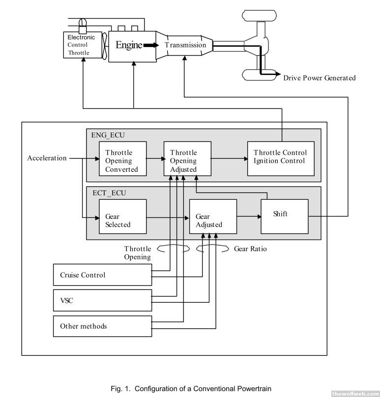
You've got an accelerator pedal position sensor signal feeding into two control paths, and then compensation algorithms for shifting, traction/stability control, vibration concerns, etc. Well that gets really complicated, especially as you add more control modules. Integrated control provides a more elegant solution:
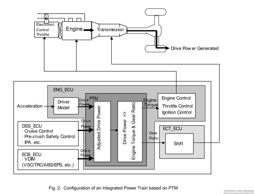
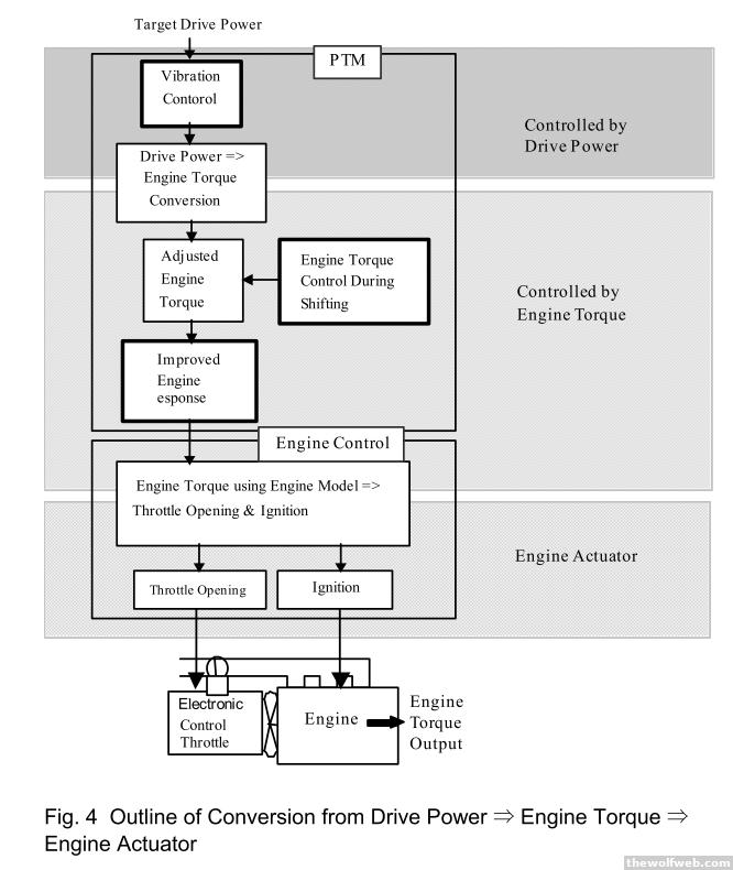
That's Toyota's implementation of integrated powertrain control. You utilize models and have the integrated controller coordinate the transmission and engine to achieve the target wheel torque/power. That also feeds into the engine dynamics control (stabilty control etc). The integrated engine controls help reduce vibration and fix the torque drop off between shifts if that's what the calibration calls for. You have to have a model to transfer target drive power into a torque request, and then a model to execute the torque request through actuator commands.
This system was implemented on the AA80E transmission used in the Lexus LS and IS-F and has probably trickled down to most vehicles Toyota makes for this market by now. 3/17/2012 8:31:05 AM |
arghx
Deucefest '04
7584 Posts
user info
edit post |
The GM "Turbo-Jet" engine family, including the 396 and 427 cubic inch variations, replaced the venerable 409 V8. This engine family improved intake airflow through a better combustion chamber design and valve arrangement:
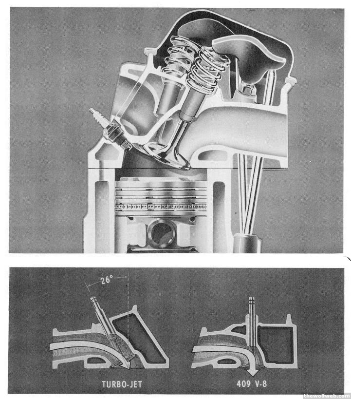
You can see that the Turbo-Jet engines (above, and left) used a wedge-shaped combustion chamber with a more gradual transition from the intake runner to the valve and port itself. 3/19/2012 9:03:43 PM |
arghx
Deucefest '04
7584 Posts
user info
edit post |
The Mazda 6 uses an Aisin 6 speed automatic (FWD/transverse) transaxle that has similarities with many other 6 speed transmissions in the industry.
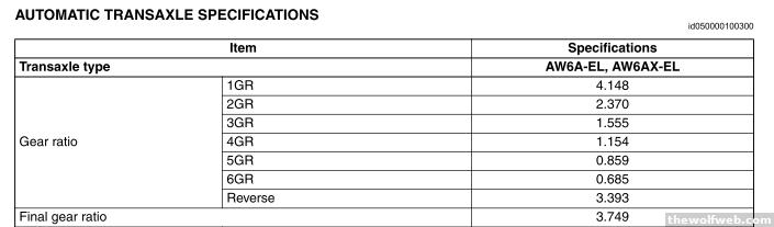
Modern 6 speed (or greater) transmissions utilize a Ravigneaux gearset . A Ravigneux gearset has a front and rear sungear, a shared set of pinion gears and an additional set of pinion gears used only for the rear sun gear. A diagram illustrates better:
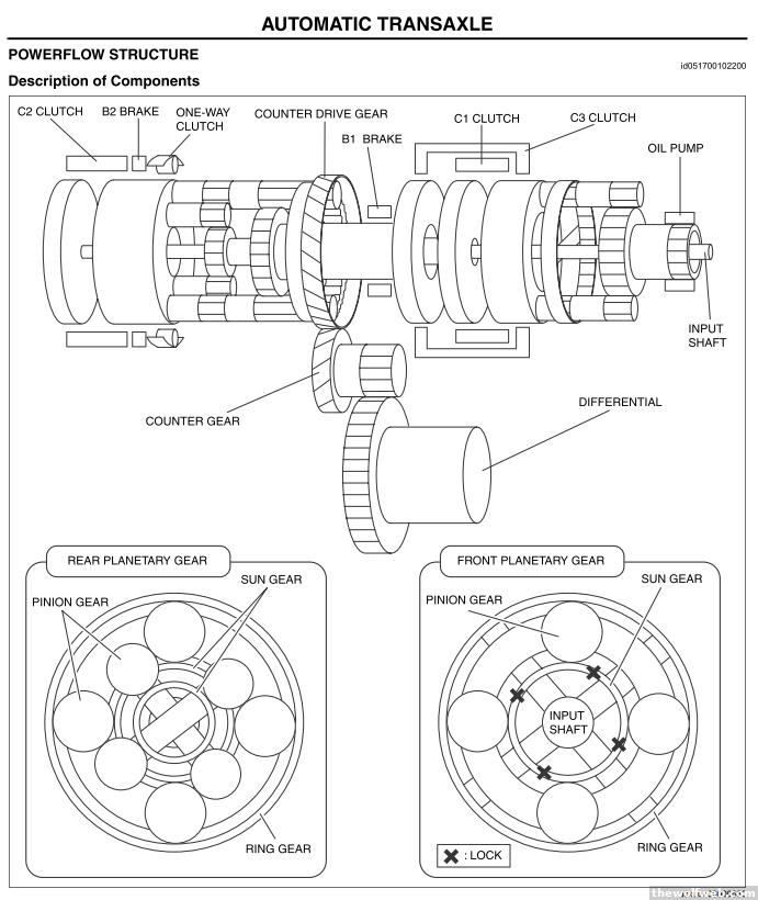
You will see clutches and brakes utilized to engage or hold stationary different elements of the gear system. This transmission uses a brake band/servo (B2) to hold the rear pinion carrier but many competing designs don't use bands at all anymore. These diagrams show powerflow for 1st gear, 4th gear, and reverse:
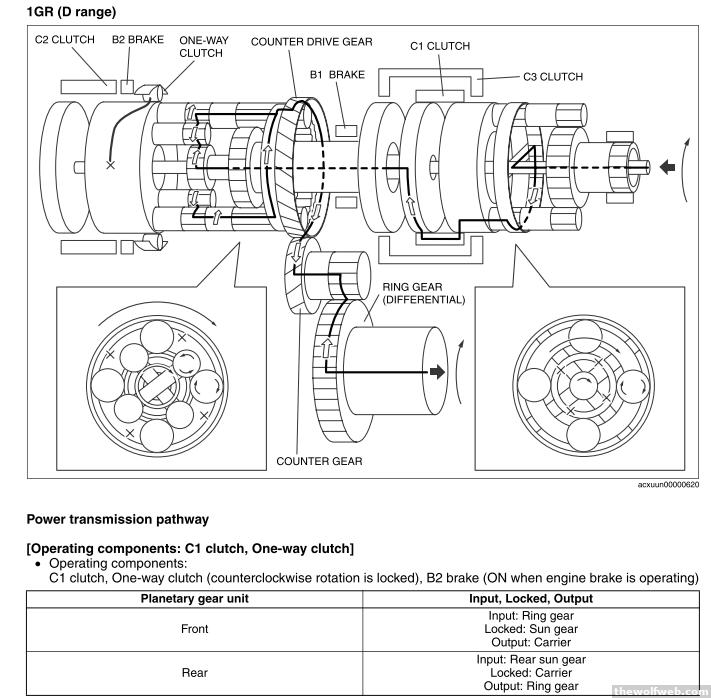
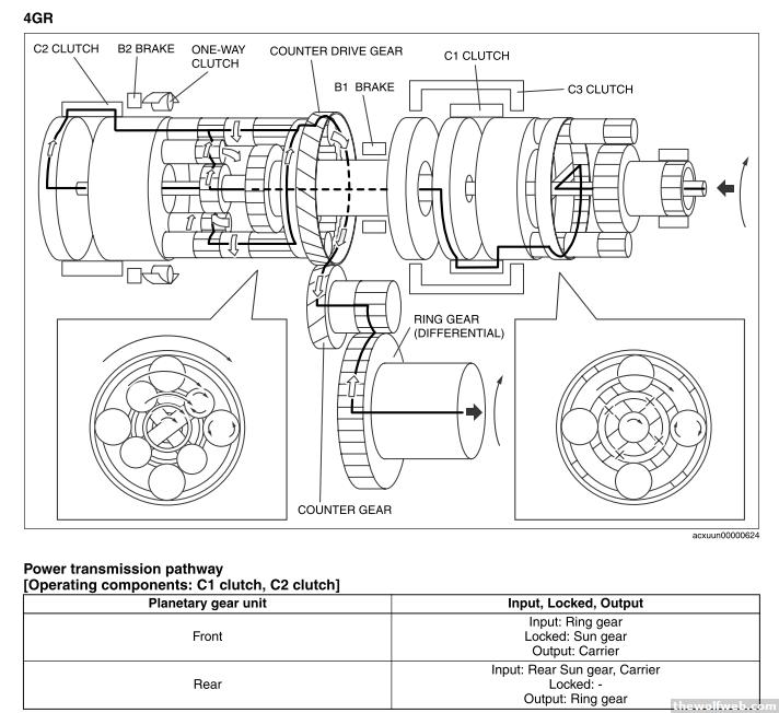
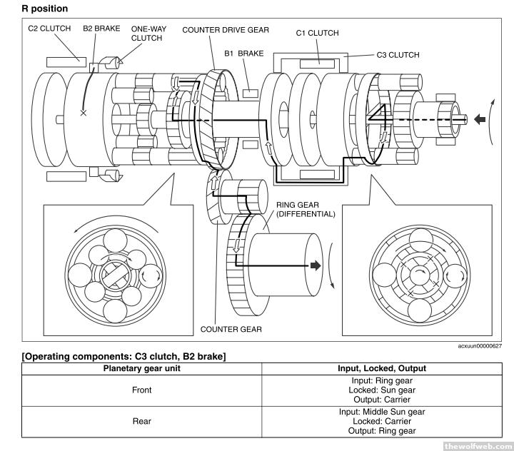
As you can see, it's pretty damn complicated.
[Edited on March 25, 2012 at 11:17 PM. Reason : .] 3/25/2012 11:16:42 PM |
arghx
Deucefest '04
7584 Posts
user info
edit post |
On page 2 I mentioned hot-wire mass airflow meters. There are two types of these meters: one in which the sensing wire samples directly in the main stream of intake air, and another where the air is routed into a bypass passageway. Both have their own set of tradeoffs in terms of flow restriction, power consumption, and sensitivity to flow and pulsation effects.
For a MAF sensor sampling directly from the main air stream, a mesh of some sort will be found in front of the wire. The mesh is intended to condition the airflow in front of the wire in order to have a more accurate signal. The chart from an old Bosch study shows the sensitivity of this type of MAF sensor to not having a mesh. At low airflow levels (solid line), the sensor reading can deviate greatly.
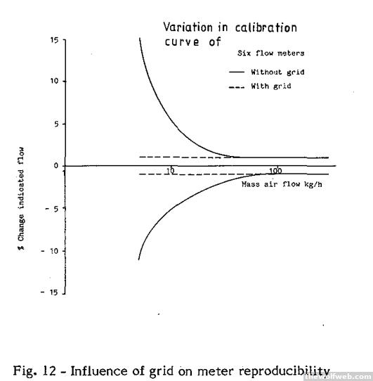
The design of the sensing wire and MAF housing affect this sensitivity. 3/27/2012 8:34:02 PM |
arghx
Deucefest '04
7584 Posts
user info
edit post |
The Bugatti Veyron Grand Sport and Audi R8 are both Volkswagen supercars in a way but I find their choices of suppliers interesting:
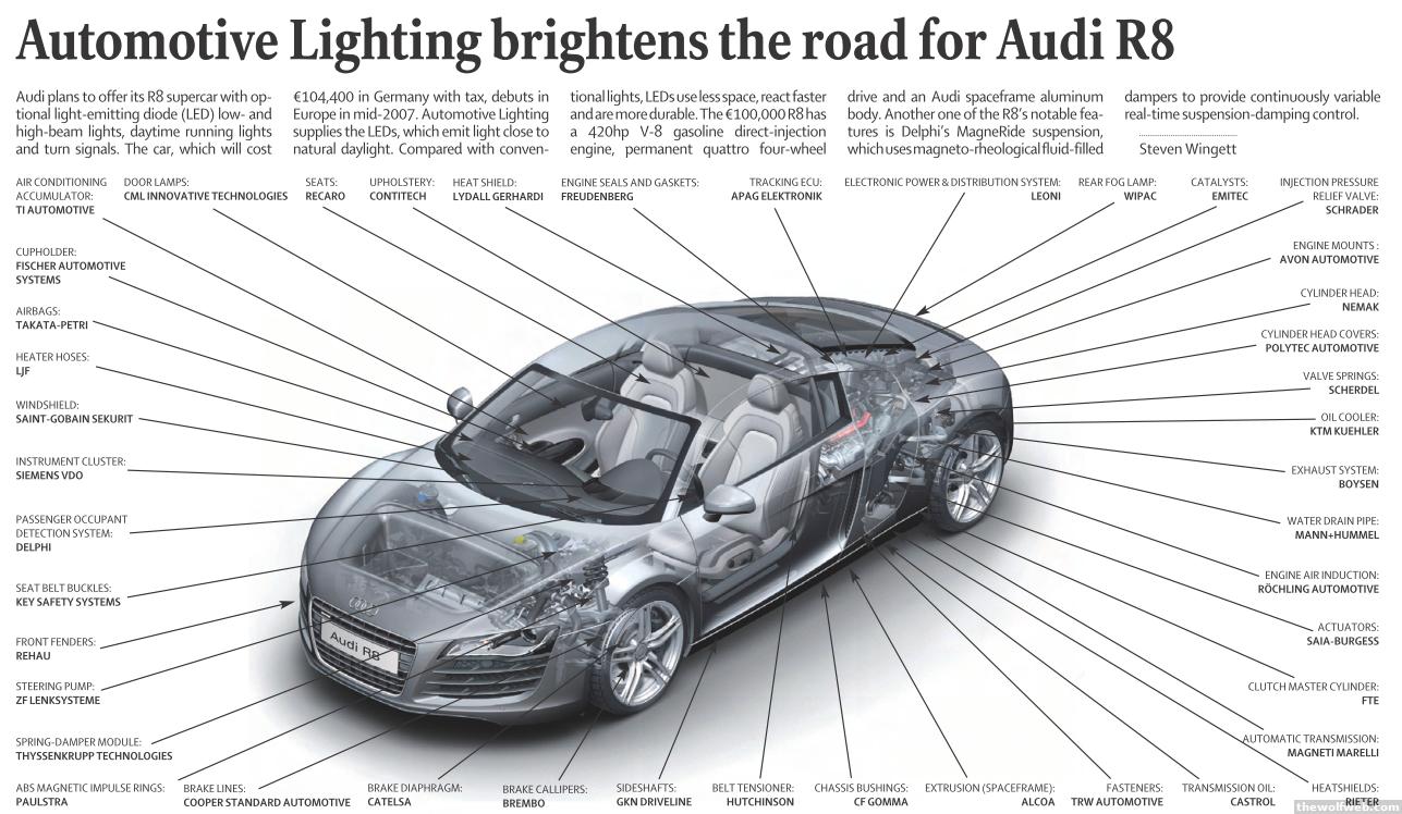
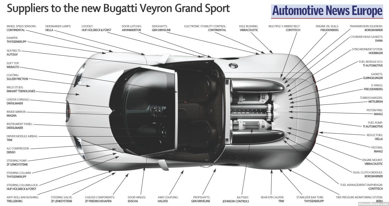
There are a few random Japanese and American companies thrown into the mix. I wonder how many of those parts were actually made in Europe? 4/1/2012 12:18:50 PM |
sumfoo1
soup du hier
41043 Posts
user info
edit post |
HALP!!!
the new gt500 is making 650 whp on 15psi out of a 5.8 liter
The new ford racing supercharged 5.0 makes 624 hp on 9psi .
what did they fuck up on the gt500 to make it have more displacement and need 6psi more to reach +26 hp over the supercharged gt.
Do the heads suck? Do the cams suck? wtf? 4/6/2012 9:02:30 AM |
arghx
Deucefest '04
7584 Posts
user info
edit post |
need more info on this 5.0. Also, the GT500 should be actually SAE certified at this power level. I am curious about how they arrived at the 5.0's numbers and under what conditions they were using to get those numbers. I'd also like to see the power and torque bands for both, with more specs on all the differences between the exhaust systems, emissions levels, NVH levels, and durability testing.
What I suspect is that the GT500 is quieter, cleaner (in terms of emissions), much more durable and thoroughly tested, and probably has a broader torque band.
[Edited on April 8, 2012 at 9:25 AM. Reason : .] 4/8/2012 9:17:14 AM |
sumfoo1
soup du hier
41043 Posts
user info
edit post |
http://www.autoblog.com/2012/04/07/ford-racing-reveals-its-latest-mustang-project/
http://www.fordracingparts.com/parts/part_details.asp?PartKeyField=12402
more durable? yes probably it's lower compression and larger displacement.
cleaner ? Maybe that's really up to the tune the coyote hasa very efficient combustion chambers and the best flowing heads ever made for a small block ford.
Quieter? Doubtful, a twin screw at 9 psi vs a roots at 15psi. I don't see how the engine could possibly be quieter.
[Edited on April 8, 2012 at 12:19 PM. Reason : .] 4/8/2012 12:13:03 PM |
sumfoo1
soup du hier
41043 Posts
user info
edit post |
http://www.mustang50magazine.com/techarticles/m5lp_1105_ford_mustang_kenne_bell_supercharger_5_0_coyote_vs_5_4_condor/viewall.html
Interesting article. Pretty much compares the 5.0 withy the 5.4 with the same blower. My favorite part is at the end where they say they never ran the 5.0 on the dyno with over 15 psi because it blew up........... The oil pump because the new lower pulley/harmonic balancer didn't agree with it.
I would have thought with 11:1 compression at 15psi that the motor would actually just blow up all together not just the oil pump. This thing must be a friggin tank of an engine. 4/9/2012 6:55:08 AM |
arghx
Deucefest '04
7584 Posts
user info
edit post |
bump by request from Air, who wanted to talk about ABS systems in the context of an ABS retrofit.
Please provide as many details as possible... 10/20/2012 4:25:56 PM |
Air
Half American
772 Posts
user info
edit post |
Well, hoping for some more theory from someone who understands better than me how the electronic signals work, but here is what I understand so far:
My goal is to retrofit ABS of some sort onto my 93 240sx.
Here is the fluid diagram of the braking system with and without ABS
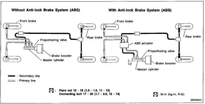
Notice the rear brakes are controlled as a unit. This is to prevent adding yaw to the car by unevenly braking the rear wheels individually. Even a 4 channel ABS system will brake the rear wheels together, the 4th channel is utilized for traction control and not ABS.
Here is the Hydraulic circuit inside the ABS Actuator unit (commonly referred to as the "Pump")
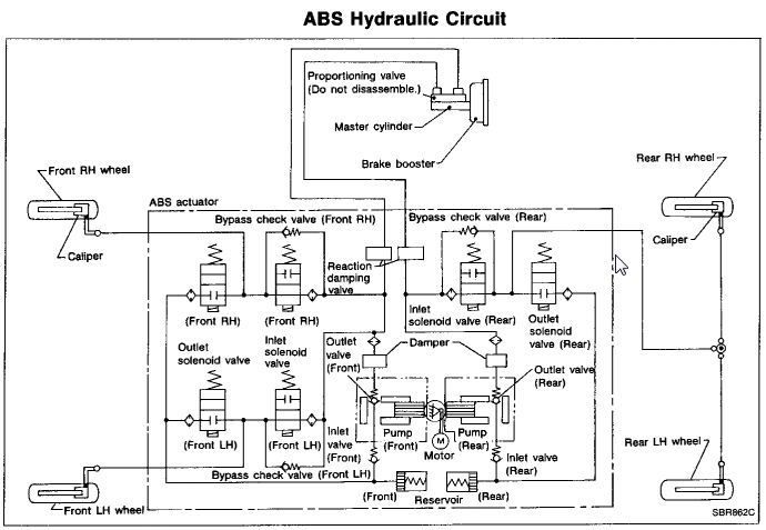
Fluid comes in already pressurized and biased (rear gets less pressure than the front)
The Actuator operation is described here:

During normal operation, the Inlet valve is open and the outlet valve is closed. This allows direct master cylinder pressure to reach the caliper.
When the Inlet valve is switched "ON", the circuit between the caliper and the actuator is cut off from the rest of the system. Whatever pressure is in the caliper at the time will remain in the caliper while this valve is in the "ON" position.
When a large deceleration is seen (wheel rotational speed decrease) the pressure to the caliper is reduced to prevent the wheel from stopping (car moving but wheel not rotating). This is accomplished by switching the inlet valve and outlet valve to the "ON" position. Even though the drivers foot is still on the brake pedal, the pressure is reduced by the pump pushing fluid back into the master cylinder (hence why the pedal pushes back against the drivers foot)
When the resulting acceleration in wheel speed is seen, the pressure to the caliper is increased again by closing both valves (the normal position). This allows master cylinder pressure to reach the caliper.
The important thing to notice here is that the hydraulic pressure used to squeeze the pads into the caliper is always generated mechanically by the drivers foot. The "pump" actually FIGHTS against the drivers foot in order to reduce braking pressure. When you mash the pedal in your car hard enough to engage ABS, the vibration you feel in the pedal is the pump forcing your foot away from the firewall. In this system, a ABS system failure will only result in ABS not working, not the entire braking system failing.
The valves switching from off-on-off-on ect is the noise that is heard. THe frequency of the on-off-on-off cycle is important, as the faster it can react the more closely it will approximate a driver who is "threshold braking".
The wheel speed is determined by a reluctor ring and a sensor. The sensor consists of a magnet wrapped with copper wire. As the reluctor ring passes by the sensor, it generates a sine-waveform. As the speed of the wheel increases, the frequency of the waveform also increases. This is the part of the system that I do not fully understand.
I am not sure how the computer accounts for the rapid change in wheel rotation. Does it convert waveform frequency into "rotations per second"? The reasoning behind my inquiry is that finding 240sx ABS is difficult, but finding Q45 or J30 ABS is easy. I am not sure about the number of teeth on Q45 reluctor rings vs 240sx reluctor rings. Would this matter to the final system? 10/21/2012 7:05:38 PM |
smoothcrim
Universal Magnetic!
18917 Posts
user info
edit post |
are you wanting the abs for extra safety on the street? I've never wanted it for a track application due to extra chassis input from the pulsing upsetting the suspension 10/21/2012 8:18:04 PM |
arghx
Deucefest '04
7584 Posts
user info
edit post |
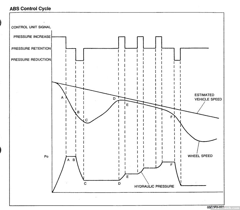
What you described is almost every late 80s/early 90s ABS system on a front engine, rear-wheel drive car. It's exactly like an FD Rx-7 for example; Nissan and Mazda probably had the same supplier. Here's a nice illustration of these oldschool ABS controls at work:
| Quote : | | "Notice the rear brakes are controlled as a unit. This is to prevent adding yaw to the car by unevenly braking the rear wheels individually. Even a 4 channel ABS system will brake the rear wheels together, the 4th channel is utilized for traction control and not ABS." |
The reason you have a 3 channel system where the rear axle is controlled together, is primarily for cost. It's just cheaper to do it that way. I suppose you can boil almost every engineering decision down to money in some way.
It kind of depends how you are looking at it though. If you are comparing it to other 20 year old systems, then yes. You can get away without a 4 channel. The NSX had a 4 channel system though. Where this whole situation gets murky is, looking at it in the year 2012, ABS, traction control, electronic brakeforce distribution, torque vectoring, and stability control are all kind of integrated concepts. They're part of a bigger picture. But we need to go back in time to the late 80s here for this discussion. So we can get bogged down in semantics and comparisons of literally decades worth of technology differences.
These oldschool systems just control wheel slip ratio within some range using a basic controller. For the most part they don't calculate torque, yaw rate, steering angling, etc. They don't have access to the information they need to do anything more. Modern systems have a bunch of modules talking to each other and integrate much more sophisticated calculations.
| Quote : | "The wheel speed is determined by a reluctor ring and a sensor. The sensor consists of a magnet wrapped with copper wire. As the reluctor ring passes by the sensor, it generates a sine-waveform. As the speed of the wheel increases, the frequency of the waveform also increases. This is the part of the system that I do not fully understand.
I am not sure how the computer accounts for the rapid change in wheel rotation. Does it convert waveform frequency into "rotations per second"? The reasoning behind my inquiry is that finding 240sx ABS is difficult, but finding Q45 or J30 ABS is easy. I am not sure about the number of teeth on Q45 reluctor rings vs 240sx reluctor rings. Would this matter to the final system?" |
Question: Can I swap a 12 tooth crank position sensor pickup in for a 24 tooth crank position sensor?
Answer: it's a bit of a trick question. It depends on the design and how fast it's spinning.
The reason I bring this up is because the 24 tooth crank angle sensor on a 2nd gen Rx-7 produces the same waveform as the 12 tooth crank angle sensor on a 3rd gen Rx-7. The difference is that the 24 tooth sensor is driven at half the speed because it runs off a distributor-style drive gear. So the question for you to think about is, will the waveform be the same?
Let's look at this diagram from the 91 NSX service manual which illustrates an ABS speed signal waveform. It's basically the simplest/cheapest electronic speed sensor you get... it only counts # of revolutions, like an old distributor signal. It doesn't resolve position, like a crank or cam angle sensors.
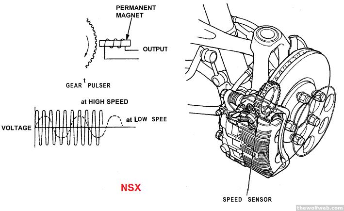
does that clear things up? Have you tried the obvious--going to NAPA etc and asking for ABS reluctor rings for a 240sx? You're rolling the dice a little bit but if you can't find a used one, you can't find a used one.10/22/2012 12:01:23 AM |
sumfoo1
soup du hier
41043 Posts
user info
edit post |
Know anything about roll cages and the ability to build one suitable for an 8.5 sec+ car in NHRA, then meet the typical standards for NASA & SCCA too ? 11/5/2012 8:41:57 AM |
Dr Pepper
All American
3583 Posts
user info
edit post |
^I'd refer to each respective organization's handbook, first, and look for cross-references or similarities as far as design goes. (not to steal ray's thunder) 11/5/2012 10:01:51 AM |
arghx
Deucefest '04
7584 Posts
user info
edit post |
What he said. ^ 11/6/2012 10:30:59 PM |
sumfoo1
soup du hier
41043 Posts
user info
edit post |
yeah... i did....
NHRA is over kill for compared to the rest but the tube locations aren't where they want them so i don't know how it would go. 11/7/2012 7:18:30 AM |
Dr Pepper
All American
3583 Posts
user info
edit post |
you talking about lateral bracing? 11/7/2012 8:37:34 AM |
sumfoo1
soup du hier
41043 Posts
user info
edit post |
yep.... not just the hoops 11/7/2012 12:34:16 PM |
sumfoo1
soup du hier
41043 Posts
user info
edit post |
ok... so mustang 2 style suspension vs strut-type? 11/19/2012 11:53:37 AM |
jawhitak
Veteran
328 Posts
user info
edit post |
^ better yet, just go ahead and cover everything! trailing arm, wishbone, multilink, macpherson, cross beam, solid axles w/ leaf springs, w/ coils, w/ watts link, etc. 11/19/2012 2:01:03 PM |
Dr Pepper
All American
3583 Posts
user info
edit post |
^bah
strut like 'drag-car' struts, or 'OEM car' struts? 11/19/2012 2:39:37 PM |
sumfoo1
soup du hier
41043 Posts
user info
edit post |
Struts like coilovers on a new mustang would be.
Told you, jack of all tracks. 11/19/2012 3:00:06 PM |
arghx
Deucefest '04
7584 Posts
user info
edit post |
I'd have to dig up some stuff... my knowledge of 70s solid axle passenger car suspensions is not especially deep, and to be honest so far I haven't found the topic interesting enough to make it a high priority-- discussing it is like listening to geezers argue about carburetors.
I've been looking into early mass produced turbocharged engines lately (60s, 70s, and early 80s). It's actually pretty relevant to both production and modded engines today. There's a lot of interesting nuggets to be found. Did you know the first Porsche 911 turbo had a 6.5:1 compression ratio and external wastegate running over 11psi boost?
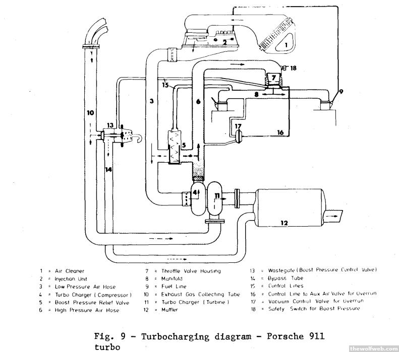

[Edited on November 19, 2012 at 8:30 PM. Reason : turbonium] 11/19/2012 8:13:19 PM |
sumfoo1
soup du hier
41043 Posts
user info
edit post |
None of what I mentioned is solid axle.
Basically macpherson strut or ~meh double wishbone. 11/19/2012 11:28:30 PM |
arghx
Deucefest '04
7584 Posts
user info
edit post |
Mustang II has a solid rear axle, like every other Mustang except forgettable Cobra independent rear suspension. So that's what I thought you meant.
[Edited on November 20, 2012 at 5:51 AM. Reason : Mustang "2" = 1974-1978 Pinto-based Mustang] 11/20/2012 5:39:50 AM |
sumfoo1
soup du hier
41043 Posts
user info
edit post |
Sorry I'm talking front :-) rear I'm doing triangulated 4 link with a watts link 11/20/2012 6:28:47 AM |
sumfoo1
soup du hier
41043 Posts
user info
edit post |
The main reason for the gt500/ vs coyote gt hp discrepancy is simple, it's not a vvti engine and has some boreing cams for emission. Obviously meaning its got a completely different set of heads on it. AAaannnnnddddd it's a spray bore engine which I still don't trust after the Lincoln/jag 4.0 fiasco.
Weisco is making a 5.8 stroker kit for the 5.0 though. 11/27/2012 6:58:48 AM |
Dr Pepper
All American
3583 Posts
user info
edit post |
'splay' bore? 11/27/2012 7:20:24 AM |
sumfoo1
soup du hier
41043 Posts
user info
edit post |
nope.... spray bore...
http://www.sae.org/mags/aei/7624
last time they did this was the teflon-like shit on the lincoln blocks... it allows them to not have to run sleeves in aluminum.
my feelings are as follows...
great it helps hold piston friction... but is the bore it's -self as rigid as when it was sleeved?
but still this is essentially a welding wire spray gun... which is fucking awesome and i want one waayyy cooler then the old Nikasil-coated cylinder crap.
look mahh... the black shit on your pans.... now... in my engine...
(waiting for our resident porsche-ophile to come in and exclaim how it works fine for them.)
[Edited on November 27, 2012 at 8:11 AM. Reason : .] 11/27/2012 8:01:45 AM |
sumfoo1
soup du hier
41043 Posts
user info
edit post |
Hey arghx
I would like some lessons in quench!!
4/25/2013 10:16:48 AM |
arghx
Deucefest '04
7584 Posts
user info
edit post |
I've been away from Tdub for a while. I'm actually in Raleigh this weekend for a wedding.
What do you mean by quench? I think people use the term "quench" as a positive thing when they are referring more to squish flows. Basically, you've got gas flows that occur near the top of the compression stroke that create turbulence. The turbulence influences combustion efficiency and knock resistance. Typically you'll see it on the edge of a combustion chamber from the shape of the head and the piston, when people talk about the "quench zone." On a diesel, squish flows work with swirl flows for improved mixture distribution.
"Quenching" as I think of it, is when a flame is extinguished, leading to unburned gases. Squish could lead to quench, but quench doesn't always lead to squish. Or at least, that's the way I'd like to think about it. I think they're talking about areas designed to induce squish flow, a side effect of which may be quenching. Generally speaking, quenching a flame isn't a good thing, but the right kind of turbulence (squish, swirl, tumble) is.
A squish-oriented combustion chamber on a gas engine is starting to become an outdated design used mostly for port injected engines. For direct injection, high tumble flow is the trend, at least for DOHC engines. The new direct injected K24W Honda engine (new Accord) is a high tumble concept. The new GM smallblock (Gen V LT1 etc) uses a significant amount of swirl flow but that is a totally different combustion chamber shape. 5/3/2013 9:13:36 AM |
sumfoo1
soup du hier
41043 Posts
user info
edit post |
squish flows.
Thinking about putting a .080 head gasket on a .030 on a 9.6/1 compression engine down to a 8.6/1 compression to turbo it (both at a later date).... what issues will be cause on a wedge engine...
Its got 88cc heads -17 cc dish on a big block ford. 5/3/2013 10:26:39 AM |
arghx
Deucefest '04
7584 Posts
user info
edit post |
dude, in my experience... the things that cause "issues" on custom turbo cars are
1) overboost & lack of overboost protection (boost cut, fuel cut, etc): wastegate hose melts etc
2) insufficient safety margin in ignition timing, see #3.
3) inability for tune to compensate for changes in weather or engine conditions. Summer turns to fall, car feels really fast right before it blows up.
the rest of that shit doesn't matter nearly as much. 5/3/2013 11:06:06 AM |
sumfoo1
soup du hier
41043 Posts
user info
edit post |
10-4... .
she's stand aloned with boost control and timing control.
 5/3/2013 11:09:44 AM |
arghx
Deucefest '04
7584 Posts
user info
edit post |
You've probably read a lot of stuff on the internet about knock, and maybe preignition. You know that they're undesirable for a spark ignited combustion engine - they can make noise, they can damage your engine if severe enough. We know knock and preignition are undesirable explosions, explosions that happen when we don't want them to happen. What exactly is happening in the cylinder though? Let's look at knock and preignition from a combustion perspective. First we need a brief introduction to combustion pressure and how it relates to spark timing. Then we can look at what happens to cylinder pressure during a significant knock event, and finally we can discuss what serious preignition event looks like.
Spark Timing, Cylinder Pressure, and Combustion Phasing
The plug creates the spark, and then the mixture begins to burn. For simplicity's sake, let's take combustion speed/burn rates out of this part of the discussion. At low speed/low load I can advance my spark very far past MBT (minimum spark advance for best torque) without encountering knock. MBT typically has the peak pressure located at about 11 degrees after top dead center firing. You can see in the image below the combustion getting more and more advanced.
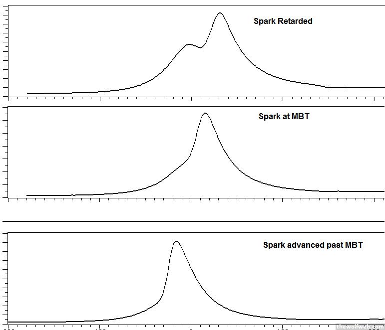
Now retarded combustion has this characteristic "double hump." What happens is, the first hump (looking left to right) is the compression from the piston reaching TDC. My burning is very retarded due to spark timing, but also due to burn rates which are a factor I won't get into. The pressure begins to drop as the piston moves downward, until enough burning begins and the pressure rises again--hence, the double-hump.
Why would I retard my combustion from MBT? I need to reduce knock, and in some cases I might need to raise exhaust temperatures to spool up a turbo or warm up a cat. The more knock limited the engine is, the more of you will see this characteristic double-hump pressure trace as spark is retarded. Retarded combustion lowers the peak cylinder pressure, which may be desirable if I don't want to stress the mechanical components too much (bearings, rods, etc).
MBT combustion has a single hump with significantly higher peak pressure then retarded combustion even if there is no knocking. It's a single hump because burning is occuring much closer to when the piston is at TDC, so the pressure of compression combines with the pressure of the combustion.
When the combustion is advanced is past MBT, you get much higher peak combustion pressures and you can see the characteristic "lean" to the left.You don't have to be knocking to have high cylinder pressure. Under normal circumstances there is no reason to advance combustion past MBT. Now let's look at what happens when I start to knock.
Knocking Combustion Pressure
If the spark is too advanced for the engine speed & load for a given fuel, the gases at the end of the combustion chamber will explode before the normal flame arrives. Knock has different levels of severity. The more severe it gets, the more likely you will hear it audibly, and the higher the peak cylinder pressure will be.
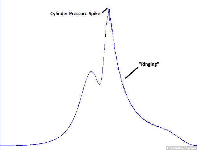
In the image above, the engine is knocking significantly but probably not enough to damage the engine and probably not enough to be heard over normal engine sounds without a microphone. The severity of the cylinder pressure spike is called the knock peak while the amount of "ringing" is called the knock intensity. There are other ways to characterize knock but those are the main metrics that rely on actual cylinder pressure.
This pressure trace isn't going to immediately break anything, but a knock sensor will probably judge it as knock. Somebody somewhere had to make a judgement call as to what constitutes severe enough knock for the knock sensor to react. The knock sensor can't read the cylinder pressure, only the vibration in the engine. As the engine speed increases, both the engine vibration and the cylinder pressure get noisier.
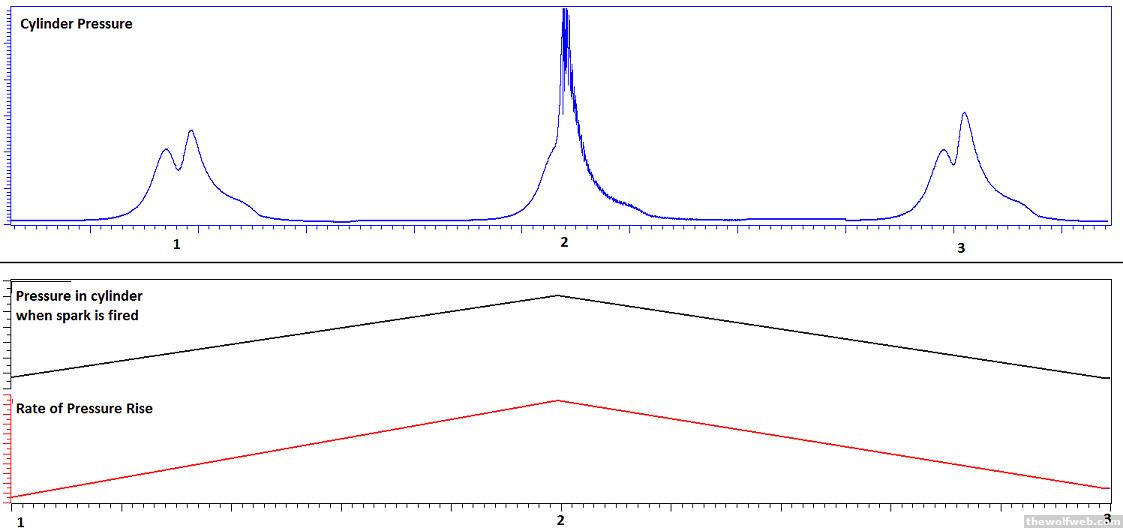
Severe Preignition
Preignition occurs when an explosion happens before the spark plug fires. This isn't always a major problem, but severe events can happen at high load for a number of reasons. Maybe some deposits broke off inside the engine. Maybe a spark plug overheated. Maybe some debris got into the engine. There are a bunch of causes for preignition, but I want to focus on how the cylinder pressure behaves in the event of a severe preignition event.
Here are three major characteristics of severe preignition:
1) high peak combustion pressure - this is can damage your engine
2) high rate of pressure increase inside the chamber - this is a major factor in the audible noise (metallic sound)
3) high pressure at the time of ignition - this is one of the main ways we know it's preignition and not just regular old spark knock.
Below is an image showing three successive pressure combustion cycles for the same cylinder. Cycle #2 has severe preignition. The rate of pressure rise and the pressure at ignition is much higher than the other two cycles (the lower chart isn't crank angle based, don't look at it the same way as the upper chart).
If we zoom in on the preignition event and overlay the ignition coil current trace, we can see cylinder pressure already shooting up when the coil discharges.
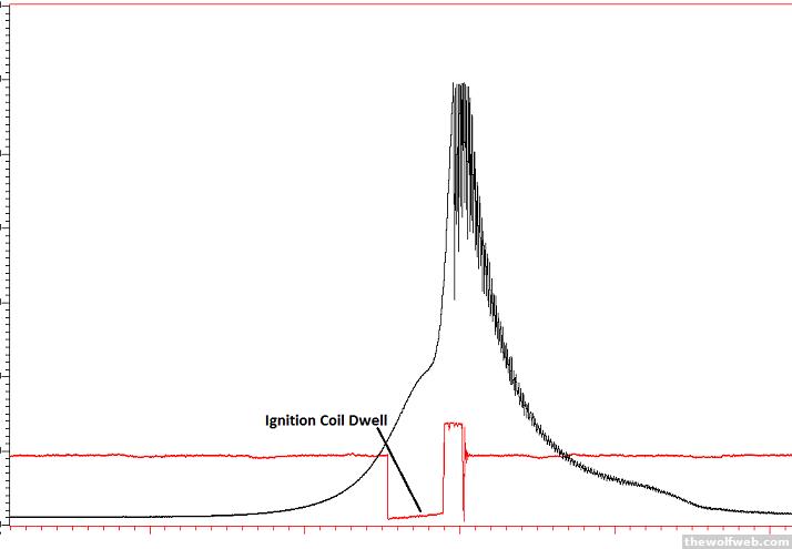
Compare that to the image below, which is the same scaling. The coil discharges and then there is a delay until enough burning happens to raise the cylinder pressure.
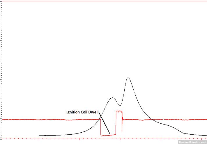
You can see that there is a significant difference between a severe preignition event, the kind that can definitely damage your engine, and a moderate knock event which might call for retarding spark timing. Of course, a severe knocking event can also cause high peak combustion pressures and noise. However, unlike preignition a severe spark knock event will not have that same characteristic high pressure at the time of ignition and probably not as fast of a pressure rise rate. I hope this clears up some misconceptions about these two types of abnormal combustion. 9/3/2014 9:08:57 PM |
sumfoo1
soup du hier
41043 Posts
user info
edit post |
Cool where do I get a head with provisions for a combustion chamber pressure sensor :-) 9/3/2014 9:20:17 PM |
arghx
Deucefest '04
7584 Posts
user info
edit post |
First you need $Texas 9/4/2014 8:32:27 AM |
arghx
Deucefest '04
7584 Posts
user info
edit post |
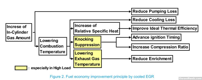
Let's talk about exhaust gas recirculation in its most modern of applications. Many of you may be thinking "ok, I'm vaguely aware that diesels use EGR now. Didn't we mostly rid ourselves of EGR valves on gasoline engines in the past 10 years?" Well, they're coming back now with the upcoming 2017 fuel economy regulations. On diesels we primarily use EGR to reduce NOx emissions. Because of the tradeoff between CO2 (fuel economy), particulates, and NOx, especially with aftertreatment, an improvement in engine-out NOx ultimately improves fuel economy.
I want to talk about EGR on turbo direct injected gas engines though. In the old days, starting in the 1970s, you had a vacuum controlled EGR poppet valve on an exhaust manifold. This would draw very hot exhaust gases into the intake manifold and back into the combustion chamber. The inert gases would reduce NOx emissions and provide a very modest fuel economy benefit. With variable valve timing/cam phasing, you can get a similar benefit from commanding overlap. So EGR valves mostly went away for gas engines.
Now they're coming back, but with coolers in-line, just like on a diesel. Some non turbo gas engines are bringing them back, like the 6.4 Hemi engine now available in Ram trucks. This draws hot exhaust from the exhaust manifold, routes it through a cooler, and then back into the intake manifold. Now Nissan is introducing cooled EGR on their 1.6 liter MR16DDT engine found in the Juke.
So for purposes of our discussion, there are two major cooled EGR configurations on a boosted gas engine: high pressure and low pressure. Diesels have these as well, as I previously mentioned.
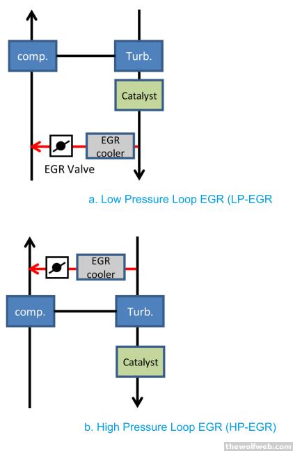
On a high pressure system, EGR comes from before the turbocharger turbine wheel, and is drawn through a cooler and into the intake manifold, typically with a poppet valve. At low speed and medium loads, exhaust backpressure will push exhaust into the intake manifold. The point of EGR introduction affects the mixing of the EGR gases among the cylinders and also affects the risk of deposits on the throttle valve. High pressure cooled EGR is good for NOx reduction and for fuel economy and steady cruising, rather than accelerating or climbing a hill. It can be typically controlled using on-board models or a simple pressure sensors to calculate EGR rates.
The problem is, that exhaust energy will be taken away from the turbo, slowing the turbo down (reducing its achievable speed). This makes it more difficult to make boost. Another concern with high pressure EGR could be catalyst failure if the EGR valve leaks and boost shoots fresh air right into the cat and overheats it. That presents on board diagnostics challenges (OBD).
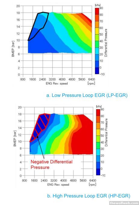
The other system is a low pressure EGR architecture. This draws EGR from after the turbocharger and pulls the EGR into the compressor inlet, usually with a butterfly valve like an electronic throttle. There's only enough backpressure to drive EGR at higher loads - more differential pressure means higher possible EGR rates. The EGR can mix very well as its drawn into the turbo compressor inlet, but the turbo needs to be able to tolerate crap being thrown at it. It needs special treatment on the compressor wheel, and it can also have icing risks in high humidity. That affects the placement of the EGR valve and design of the mixer. It can be controlled using ECU modeling but the most accurate control is with a wideband o2 sensor placed in the compressor outlet gas stream.
Low pressure EGR is intended to really help "real world" fuel economy that so many people complain about on turbo DI engines, especially an engine like the MR16DDT on the Juke. It mostly works during heavier loads at a steady state. That means towing, climbing a hill, or accelerating in high gear. Banging through gears quickly is not advantageous for low pressure EGR due to the long transit time through the engine.
Low pressure cooled EGR can reduce knock tendency at higher loads, allowing more advanced combustion. This keeps exhaust temperatures down, meaning less fuel being dumped in when you go into boost just driving around town. At higher speeds and loads the low pressure EGR can overspeed the turbine. Typically EGR rates are limited or set to 0 at full load. With low pressure EGR running, the engine needs to run more spark timing and more boost to make a given torque. It also has to cope with hotter compressor outlet temperatures; this stresses the cooling system in the vehicle. Another disadvantage of low pressure EGR is a potentially loud droning sound at medium loads. This requires noise cancellation through the speakers, some active valve in the intake box, or disabling EGR and losing the fuel economy benefit.
Both of the high and low pressure systems have two major disadvantages: they increase risk of deposits in the intake tract, intake valves, etc. They also hurt combustion stability, causing torque fluctuations. If the combustion gets too unstable, the engine feels like it's camming just driving around the road at low load (mostly low pressure EGR and internal EGR). Most "regular" drivers don't like that feeling. There are some tricks to mask that effect, like active engine mounts. At high load for low pressure EGR, too much combustion instability can lead to a surging feeling.
To reduce the combustion instability on either low or high pressure EGR, the intake port is typically designed for high swirl or high tumble. That means either a restrictive intake port (requiring more boost to make torque/power) or a tumble/swirl control valve. Cooled EGR and modern late intake valve closing Miller Cycle concepts typically require a gazillion psi boost to make the same power as simpler turbo DI designs; this is because of low effective compression ratio to reduce knock and pumping work, as well as restrictive high tumble ports and combustion chambers to tolerate high EGR rates.
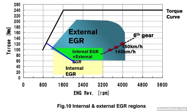
This image shows the EGR utilization on the new Juke engine. Notice that at low loads it is using overlap for hot internal EGR like a conventional engine. At mid-high loads it uses the cooled EGR. At full load it doesn't use EGR. This could be due to a design choice in turbocharger matching - the turbo would need to be sized such that it can handle the extra speed requirements of running EGR. There are disadvantages to that. Not running CEGR at full load also limits how hot intake manifold will get.
[Edited on September 29, 2014 at 11:07 PM. Reason : .] 9/29/2014 10:59:50 PM |
Hiro
All American
4673 Posts
user info
edit post |
I hate egrs. 9/29/2014 11:15:37 PM |
arghx
Deucefest '04
7584 Posts
user info
edit post |
Volkswagen is now incorporating cam phasing into their newest diesel engines. Normally on a dual overhead cam engine you have one cam controlling the intake valves and one controlling the exhaust valves. The VW new diesels have a clever design where a cam will control an intake and exhaust valve on one side of the engine:
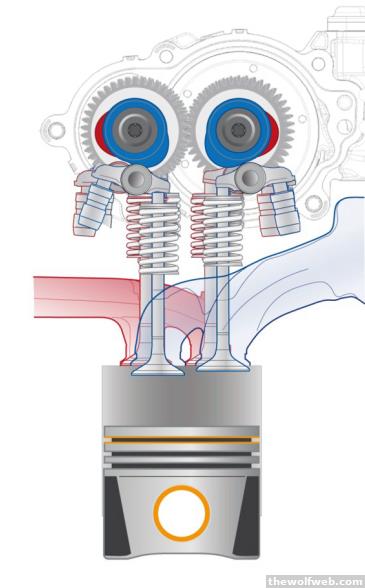
One of those camshafts can phase (I will skip details of how the actual phaser works) and one of them has fixed timing. So each cylinder has two intake and two exhaust valves, with one of each being adjustable:
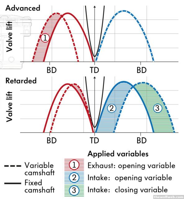
So the phaser can retard the intake valve closing of one of the valves. When I retard the intake valve closing, it lowers the effective compression ratio. This is because the intake valve spends more time pushing air back out into the intake port as it ascends through the compression stroke. With a lower effective compression ratio on a diesel, you get lower NOx emissions due to lower temperatures at firing TDC.
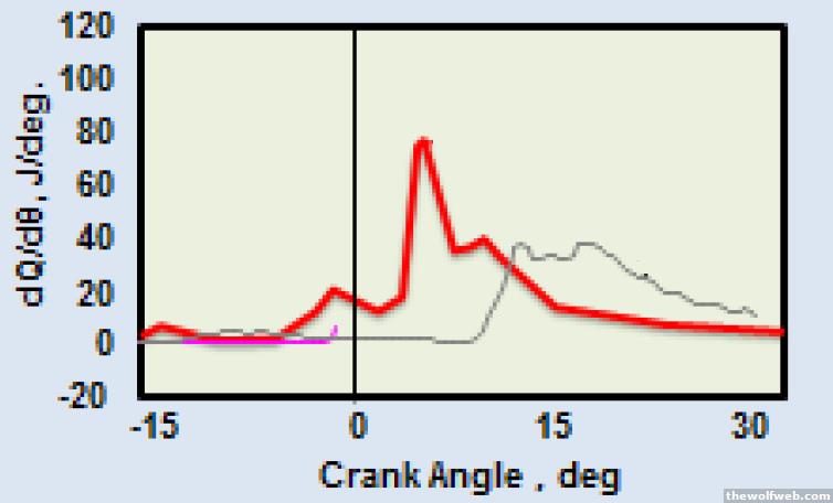
Remember, when we can lower NOx emissions, we don't have to retard injection timing on a diesel to counteract that. The image below shows combustion heat release on an engine with a higher and a lower effective compression ratio. With the lower effective compression ratio, the combustion can be advanced by moving the injection timing (sort of like advancing spark on a gasoline engine). Red line below shows earlier and faster combustion enabled by lower compression:
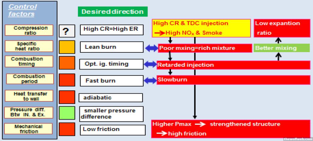
When you reduce the emissions inside the cylinder you ultimately reduce reliance on complicated and expensive after treatment (particulate filter regeneration events, diesel exhaust fluid consumption, etc). The chart below, originally discussing Mazda SkyActive diesel engines, shows some of the negative effects of high compression ratio.
Now, shouldn't a lower compression ratio hurt efficiency and fuel economy? Well, the trick here is that with this simple cam phaser we offset the lower compression ratio with a longer expansion ratio. It's a similar principle to the cam phasers on SOHC and pushrod engines, like the GM and Chrysler V8's. The exhaust valve opens later, so I get more expansion work to offset the loss in compression. We can also advance the opening of the exhaust valve, creating a stronger blowdown pulse (with lower expansion ratio). That high pressure exhaust opening during the expansions stroke can help relieve backpressure and pumping work as the turbo is spinning.
With this cam phaser in the retard position we also have a staggered opening of the intake valves, because the phaser operates on only one valve. That increases swirl. Swirl is very good for diesel combustion because it helps mixing in the cylinder. Normally a cam phaser requires valve pockets on the piston so that the valves don't collide. When you put a valve pocket on a piston engine it can disturb the swirl motion; by using the offset lift you counteract that side effect, while still gaining the benefits of lower effective compression.
Mazda also uses a simple variable valve timing system on their SkyActive-D engine. It opens the exhaust valve during the intake stroke for cold start. Hot exhaust gases from other cylinders will blow back into the engine to stabilize combustion due to the low compression ratio used on the Skyactive-D. 10/4/2014 12:33:23 AM |
Hiro
All American
4673 Posts
user info
edit post |
^ Now that's cool. 10/4/2014 9:52:12 PM |
arghx
Deucefest '04
7584 Posts
user info
edit post |
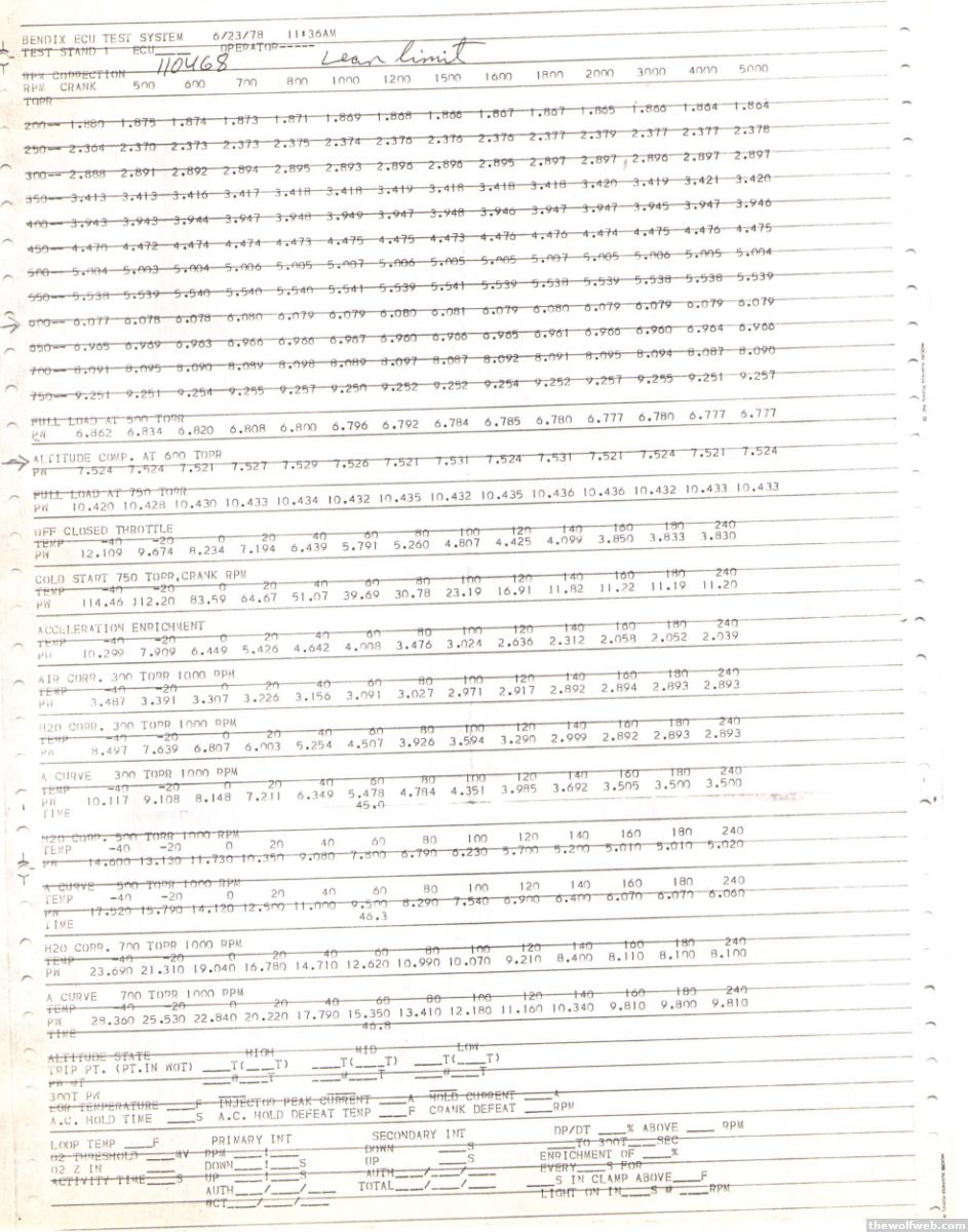
These are the maps and look up tables in the stock ECU of a 1970s Cadillac ElDorado. I snagged this from an old timer who worked for Bendix back then, when they did fuel injection for GM and were way more than just a brand of brakes you get at Autozone. I think he appreciated me listening to his stories of the good ol’ days and he let me scan it. “Maps” and “Look up Tables” are really not accurate; the stock ECU was analog and these values were input with resistors or something. It’s hard to grasp something so primitive, like trying to understand how the Egyptians built the pyramids without backhoes and cranes.
Back then they were mostly just look up tables of injection pulsewidth (firing duration of injector) versus manifold pressure (units: mm Hg, also called tor) or air/water temperature. You can even see at the bottom an area for oxygen sensor feedback, which for whatever reason wasn’t filled out. It's a primitive speed density system.
10/10/2014 11:30:21 PM |
arghx
Deucefest '04
7584 Posts
user info
edit post |
On page 2 I showed a chart that compared different types of limited slip differentials. Here are some diagrams from the front limited slip differential out of an Evo VII, which is the Helical/Torsen type.
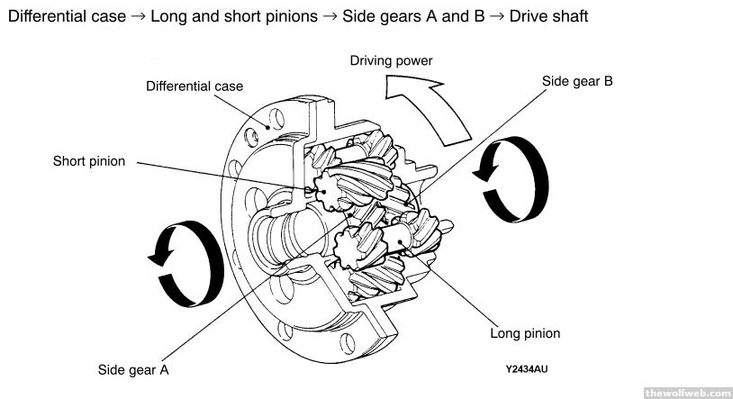
You have differential case, side gears, and pinion gears with "long side" and "short side. When you are driving straight for basic cruising, everything pretty much moves in the same direction and you don't have differences in speed or torque applied to the different gear sets.
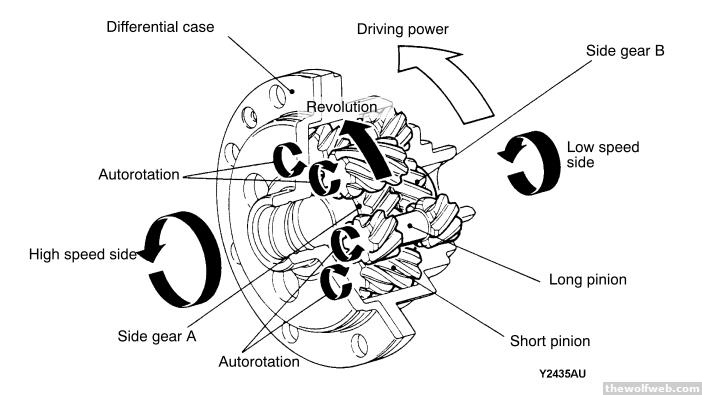
In a normal turn, there is a difference in speed between the side gears. This makes the pinion gears on the faster turning side rotate backwards so that the inner and outer wheel of the vehicle can move at different speeds.
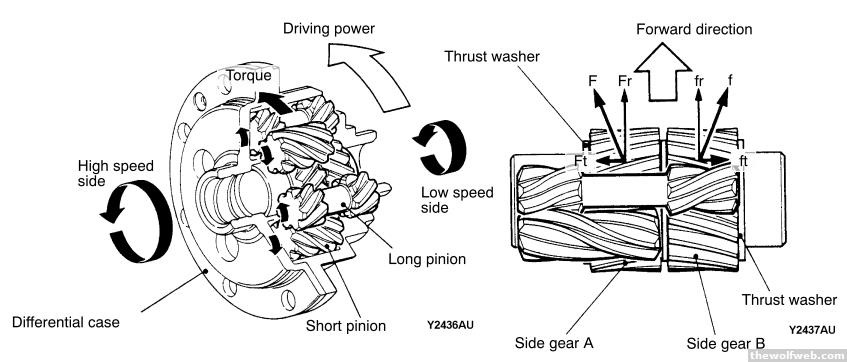
Now here's a slipping condition. Say one wheel hits ice and the other is on pavement. The wheel that hits ice would be the high speed side here, with the wheel contacting a lower friction surface. The gears are constantly in mesh, and when the high speed side slips, it creates a series of forces in the various gear sets that work against the thrust washers (axial direction) and differential case (radial direction). Remember, all the gears are connected, so they are all pushing back on one another. The gears, thrust washers, and differential case are designed so that a friction torque is generated to provide limited slip functionality. 10/11/2014 2:30:59 PM |
arghx
Deucefest '04
7584 Posts
user info
edit post |
Today you might be able to go up to 10,000 miles without changing your engine oil on a modern vehicle. People don't realize though that early automobiles required regular lubrication of the chassis, steering, and suspension components. Here is a lubrication chart for a model T:
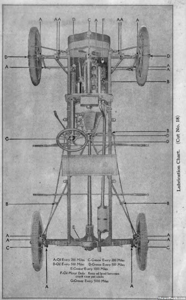
Notice how parts of the vehicle required new grease every 200 miles. Now I'm sure people slacked on that to some extent, but you can be sure that accelerated wear would occur.
Rolls Royce actually had a system built into their vehicles that would lubricate the various joints for you. This must have been a very convenient feature back then. Of course, if you owned a Rolls Royce you probably had paid staff who could lubricate the thing for you anyway. And you probably never drove your own car. And you probably had to pay to fix that lubrication feature. So maybe it wasn't as much of a benefit as it might seem. 10/11/2014 4:47:59 PM |
theDuke866
All American
52653 Posts
user info
edit post |
Ha, I remember greasing all those nipples (giggity) everywhere. Not every 200 miles, though. More like every 3000, along with the oil change intervals of the time.
Shit there are plenty of cars that call for oil changes less frequently than every 10k now. 10/11/2014 6:14:49 PM |